
Steady mechanical power
P = F × v
Where P is mechanical power at the driven surface, F is total tractive force and v is conveyor surface speed. This is a framework, not a complete motor rating.
Drive duty and transmission
Define tractive force, speed, starts, incline, acceleration and operating environment before selecting a motor, gearbox, transmission and approved control range.

First-principle duty
For a steady conveyor, mechanical power at the driven surface is the total tractive force multiplied by surface speed. The tractive force can include rolling or sliding resistance, belt or chain return resistance, product lift on an incline and other system losses. Starting, acceleration, starts per hour, gearbox efficiency, transmission efficiency and component service factors then influence the selected drive. Final selection must use the data and limits of the actual motor, gearbox, belt, chain, roller and drive components.
P = F × v
Where P is mechanical power at the driven surface, F is total tractive force and v is conveyor surface speed. This is a framework, not a complete motor rating.
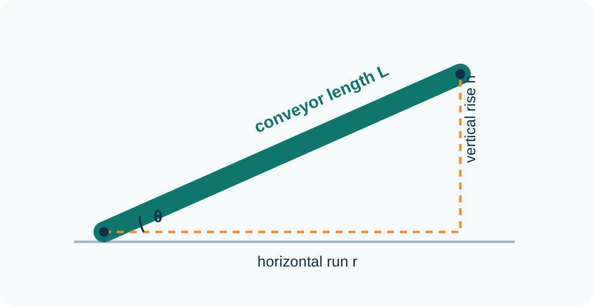
Flift = m × g × sin θ
The lifted moving mass contributes a force component along the slope. The total duty must also include conveyor and resistance effects.
n = 60v ÷ (πD)
Effective drive diameter D links linear speed to output rpm. Use the selected component’s effective diameter rather than a nominal outside dimension.
Symbols and equations are for transparent initial checks. Component selection, safety, braking and thermal validation require competent project engineering and supplier data.
Duty inputs
| Input | What to define | Why it matters |
|---|---|---|
| Moving mass | Product distribution plus belt, chain, slats, rollers or other moving parts. | Influences resistance, incline force, acceleration and supporting-component load. |
| Resistance | Friction or rolling resistance under expected alignment, tension, contamination and temperature. | Sets the basic tractive force; catalogue values must match the selected construction. |
| Incline or decline | Angle, slope length, load position and whether the conveyor can stop loaded. | Adds lift duty and may create holding, overhauling or controlled-stop requirements. |
| Speed range | Normal speed, minimum approved speed, maximum approved speed and acceleration time. | Changes output rpm, cooling, torque, product behaviour and line coordination. |
| Start frequency | Starts per hour, reversing, indexing, stop duration and starting while fully loaded. | Can control thermal duty and required service factor even when steady power is modest. |
| Environment | Temperature, moisture, cleaning, dust, mounting, ventilation and ingress exposure. | Influences motor, brake, gearbox, lubricant, enclosure and maintenance selection. |
| Failure state | Power loss, VFD fault, blocked product, emergency stop and restart sequence. | Defines whether the load must hold, coast, stop in a controlled way or be mechanically restrained. |
Gearbox and transmission
The required conveyor output speed and effective drive diameter establish an initial output rpm. The gearbox ratio then relates motor speed to that output, subject to the chosen motor, gearbox and control method. Output torque must cover the calculated tractive force at the drive radius plus the applicable efficiencies and service conditions. Check radial loads, shaft and key capacity, sprockets or pulleys, chain or belt pull, mounting orientation, backlash where relevant and the gearbox manufacturer’s thermal and mechanical ratings.
Use the conveyor engineering calculations for transparent speed and load checks, the incline conveyor page for product stability and the FAT and SAT checklist to validate loaded running and restart conditions.
Variable-speed control
Confirm the permitted motor frequency range, torque characteristic, cooling at low speed, overspeed limits, gearbox input limits, brake compatibility and the process need for acceleration or deceleration. A low surface speed may require more torque at the load while reducing motor cooling. A higher speed may exceed the approved belt, chain, bearing or gearbox condition. Where neighbouring machines share a line, agree which system commands speed and how the conveyor responds if the reference is lost.
Check motor cooling, available torque, lubricant behaviour, sensor response and whether the product remains stable rather than assuming any frequency is acceptable.
Product slip, tipping, chain tension, drive current and regeneration can be more important than steady speed. Use representative loaded trials.
Test the maximum credible loaded condition, including an incline or accumulated section, and define whether automatic restart is permitted.
Buyer questions
No. Length affects resistance and load, but the duty also depends on construction, moving mass, speed, incline, starts, acceleration, environment and component efficiencies.
Frequent starts, high acceleration, a steep incline, concentrated loads, difficult friction conditions or a loaded restart can dominate steady-running power.
No. Apply the component manufacturer’s service guidance after the real torque, speed, start frequency, load pattern and environment are defined.
A brake or other holding method may be considered where a load could move after power is removed, subject to the final risk assessment and mechanical design.
It can be technically possible in some architectures, but motor protection, matching, control modes, safety, fault isolation and maintenance consequences require project-specific design.
Measure or observe current, temperature, speed, loaded start, stop, restart and fault behaviour under agreed representative conditions, then compare the result with the approved component limits.
Project review
Send the product load, route, speed range, starts, incline, operating hours and environment so the complete conveyor drive can be reviewed.