Conveyor systems — UK specification, installation and support01494 623015 · sales@lancinguk.com

Layout and transfer engineering

Conveyor Transfer & Layout Details

Use plan and elevation drawings to control product support, guide transitions, machine interfaces, access and the operating sequence.

Plan-view conveyor transfer and layout drawing
Engineering guidance for powered conveyor specification
Loaddimensions, mass and stability
Routetransfers, curves and elevations
Controlspeed, sensors and interfaces

Plan and elevation

Show the product route and the support available at every handover.

A useful conveyor drawing identifies the product direction, centreline, conveyor top height, frame and drive position, guide transitions, sensor locations, machine interfaces, guarding and access. It should also show the minimum and maximum products that control the design.

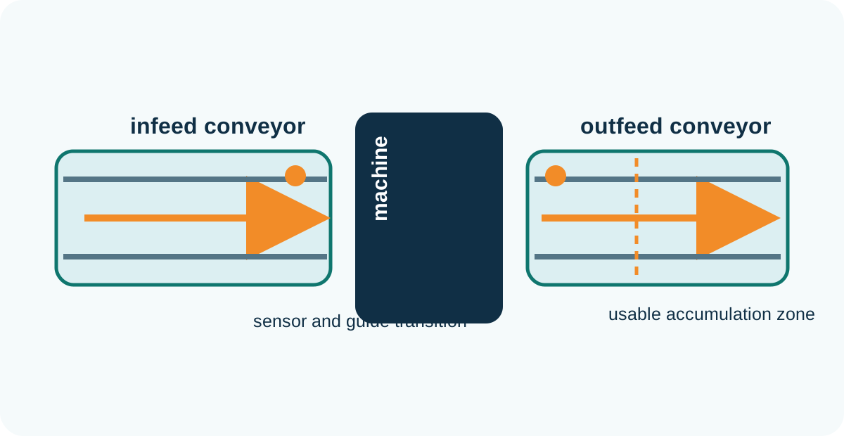
Plan-view conveyor layout with infeed, machine, outfeed, sensors, guides and accumulation
Plan view: route, direction, guide transitions, sensors and available buffer length.
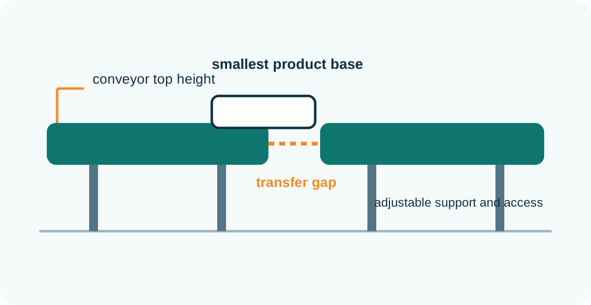
Side elevation conveyor transfer with top height, product support and transfer gap
Elevation: conveyor top height, product support, adjustment and access below the transfer.

Transfer detail

Check the smallest product in the least stable condition.

The transfer design should be reviewed in plan and side elevation. The critical product may be the smallest pack, the lightest empty container, the heaviest filled container or the format with the least rigid base.

DetailQuestions to resolveEvidence
Unsupported gapCan the leading edge and base bridge the gap without dipping or catching?Dimensioned drawing and physical sample.
Height differenceIs the product climbing, dropping or changing support surface?Top-of-belt/roller measurements under operating load.
Guide transitionDoes the product lose lateral support or experience a sharp contact point?Plan view and changeover range.
Speed relationshipWill the product accelerate, decelerate, rotate or open a gap?Speed range and representative run.
Cleaning and guardingCan the detail be cleaned and maintained without access to hazardous movement?Task review and approved isolation method.

Video reference

Observe product behaviour, not only conveyor movement.

Video is useful for reviewing stability, guide contact and transfer behaviour. Record from the side and above, include a scale or known dimension, and capture normal running, stop, restart and the least stable product.

Existing Lancing conveyor footage used as a general movement reference; final approval requires the actual project products and layout.

Continue with the layout checklist and controls, safety and washdown guide.

FAQs

Conveyor Transfer & Layout Details questions

What should a conveyor layout drawing include?

Include product direction, centreline, top height, overall dimensions, transfers, guides, drives, sensors, guarding, access and adjacent equipment.

Why are plan and elevation views both required?

Plan view shows the route and lateral interfaces; elevation shows heights, support gaps, inclines and access below or above the conveyor.

Which product should be used to check a transfer?

Use the product with the least favourable combination of base, size, mass, stability and surface condition, not only the nominal product.

How should an existing machine interface be measured?

Record finished-floor reference, conveyor top height, direction, guide opening, transfer geometry and any adjustment range.

Can a video replace a dimensioned drawing?

No. Video helps explain behaviour but does not provide controlled manufacturing or installation dimensions.

What should be agreed before drawing approval?

Agree product range, route, interfaces, maintenance access, controls, safety boundaries and the meaning of approval status.

Engineering enquiry

Apply the guidance to your actual product and layout.

Send the product range, route, output and environment so Lancing can review the conveyor requirement under representative conditions.

Send conveyor details

Interface schedule

Give every handover a number, an owner and an acceptance check.

A route drawing shows where conveyors meet, but an interface schedule records how each boundary is intended to work. Number interfaces in the direction of travel and use the same reference on the plan, elevation, control description and test sheet. This prevents a change at one handover being missed in another document.

Interface recordContentAcceptance evidence
Mechanical positionFinished-floor datum, centreline, top-of-conveyor height, nominal gap, adjustment range and direction of travel.Measured installation check against the approved drawing.
Product supportProduct base, leading/trailing support, guide opening, dead plate or roller/nose detail.Representative product crosses without dipping, catching, rotating or losing required orientation.
Speed relationshipUpstream and downstream speed ranges, intended gap change and permitted queue condition.Normal flow, controlled stop and restart observed at the defined rates.
Control handshakeRun permit, ready, blocked, fault, emergency-stop boundary, sensor ownership and reset sequence.Functional test with each expected normal and fault state recorded.
Guarding and accessFixed/movable guards, interlocks, isolation, access for clearing and maintenance responsibility.Project risk assessment and approved task/access review.
Commercial ownerParty responsible for supply, mounting, wiring, software, validation and final adjustment.Interface schedule agreed before order and updated at handover.

Use four views where the interface is critical

Plan and side elevation establish route and height. Add an end view where guide, frame or guarding clearances matter, and a detailed section where the product passes over a nose, roller, dead plate or lift-transfer mechanism. Each view should use the same interface number.

Test the least favourable product state

Choose the sample with the weakest support, least stable centre of gravity, largest dimensional variation or highest transfer load. Test normal flow, downstream stop, queued restart and any expected changeover extreme. Record video as supporting evidence, but retain the measured drawing and result sheet as the controlled record.

Close the boundary before commissioning.

Before site work, confirm who supplies final supports, levelling, guard infills, sensors, cables, signal mapping and software changes. At commissioning, check that the physical interface matches the approved revision and that the control sequence still reflects the agreed product flow. Unrecorded site adjustments should be transferred back to the final drawing and schedule.

Continue with the controls, safety and washdown guide for functional and access boundaries, and the powered-conveyor duty framework for the wider route.